ATM90E32 Power Sensor
The atm90e32 sensor platform allows you to use your ATM90E32 voltage/current and power sensors
(datasheet) with
ESPHome. This sensor is commonly found in CircuitSetup 2 and 6 channel energy meters and the Gelidus Research 2 channel power meter.
Communication with the device is done via an SPI bus, so you need to have an spi: entry in your configuration
with both mosi_pin and miso_pin set.
The ATM90E32 IC can measure up to three AC voltages although typically only one voltage measurement would be used for the mains electricity phase of a household. Three current measurements are read via CT clamps.
The CircuitSetup Split Single Phase Energy Meter can read 2 current channels and 1 (expandable to 2) voltage channel.
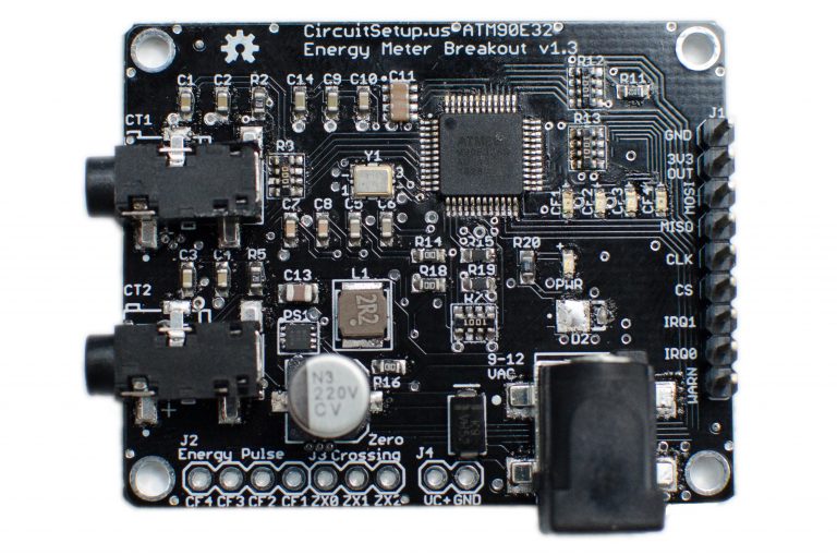
CircuitSetup Split Single Phase Real Time Whole House Energy Meter.
The CircuitSetup 6-Channel Energy Meter can read 6 current channels and 2 voltage channels at a time, this board has two ATM90E32 ICs and requires two sensors to be configured in ESPHome.
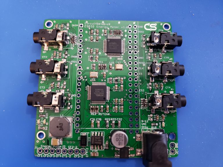
CircuitSetup Expandable 6 Channel ESP32 Energy Meter Main Board.
Configuration variables:
cs_pin (Required, Pin Schema): The pin CS is connected to. For the 6 channel meter main board, this will always be 5 and 4. For the add-on boards a jumper can be selected for each CS pin, but default to 0 and 16.
line_frequency (Required, string): The AC line frequency of the supply voltage. One of
50Hz,60Hz.id (Optional, ID): Required if using more than one
atm90e32chip with buttons for calibration, reference voltage/current fields, and phase status fieldsphase_a (Optional): The configuration options for the 1st phase.
voltage (Optional): Use the voltage value of this phase in volts (RMS). All options from Sensor.
current (Optional): Use the current value of this phase in amperes. All options from Sensor.
power (Optional): Use the power value on this phase in watts. All options from Sensor.
reactive_power (Optional): Use the reactive power value on this phase in VAR. All options from Sensor.
apparent_power (Optional): Use the apparent power value on this phase in VA. All options from Sensor.
power_factor (Optional): Use the power factor value on this phase. All options from Sensor.
phase_angle (Optional): Use the phase angle value on this phase in degrees. All options from Sensor.
peak_current (Optional): Use the peak current value on this phase in amperes. All options from Sensor.
harmonic_power (Optional): Use the harmonic power value on this phase. All options from Sensor.
gain_voltage (Optional, int): Voltage gain value to scale the low voltage AC transformer to household mains feed. Defaults to
7305.gain_ct (Optional, int): CT clamp calibration value for this phase. Defaults to
27961.offset_voltage (Optional, int): The voltage offset obtained using the offset calibration feature when current and voltage are 0 Defaults to
0offset_current (Optional, int): The current offset obtained using the offset calibration feature when current and voltage are 0 Defaults to
0offset_active_power (Optional, int): The active power offset obtained using the power offset calibration feature when current is 0 and a voltage transformer is plugged in and calibrated. Defaults to
0offset_reactive_power (Optional, int): The reactive power offset obtained using the power offset calibration feature when current is 0 and a voltage transformer is plugged in and calibrated. Defaults to
0forward_active_energy (Optional): Use the forward active energy value on this phase in watt-hours. All options from Sensor.
reverse_active_energy (Optional): Use the reverse active energy value on this phase in watt-hours. All options from Sensor.
phase_b (Optional): The configuration options for the 2nd phase. Same options as
phase_a.phase_c (Optional): The configuration options for the 3rd phase. Same options as
phase_a.frequency (Optional): Use the frequency value calculated by the meter. All options from Sensor.
peak_current_signed (Optional, boolean): Control the peak current output as signed or absolute. Defaults to
false.chip_temperature (Optional): Use the chip temperature value. All options from Sensor.
gain_pga (Optional, string): Increase this when the output of the CT clamp is too low and
gain_ctis maxed out. One of1X,2X,4X. Defaults to1X, which is suitable for most CT clamps.current_phases (Optional): The number of phases the meter has,
2or,3The 6 Channel Expandable Energy Meter should be set to3, and the Split Single Phase meter should be set to2. Defaults to3.update_interval (Optional, Time): The interval to check the sensor. Defaults to
60s.spi_id (Optional, ID): Manually specify the ID of the SPI Component if you want to use multiple SPI buses.
enable_gain_calibration (Optional, boolean): If true this enables gain calibration for voltage,
gain_voltage, and current,gain_ct, based on the values entered in the corresponding voltage,reference_voltage, and current,reference_current, reference fields. With multiple ATM90E32 sensors each one is enabled individually, and it’s buttons are mapped using an id value pair. e.g.id: chip1when more than one is defined. After running, the values are stored in chip memory and will be available upon reboot and OTA software updates.enable_offset_calibration (Optional, boolean): If true this enables fine grained offset noise 0 level calibration for voltage,
offset_voltage, and current sensors,offset_current, & power offset for active,offset_active_power, and reactive power,offset_reactive_power. Buttons are required to operate the calibration feature. With multiple ATM90E32 sensors each one is enabled individually, and it’s buttons are mapped using an id value pair. e.g.id: chip1when more than one is defined. After running, the values are stored in chip memory and will be available upson reboot and OTA software updates. Offset calibration can only be performed when all voltage and current inputs are at a 0 value. USB power is recommended. For power offset calibration, only a voltage transformer should be connected.
Text Sensor
text_sensor:
  - platform: atm90e32
    id: chip1
    phase_status:
      phase_a:
        name: "Phase A Status"
      phase_b:
        name: "Phase B Status"
      phase_c:
        name: "Phase C Status"
    freq_status:
      name: "Frequency Status"
Configuration variables:
id (Optional, ID): The ID of the
atm90e32sensor defined above. Required if using more than one sensor.phase_status (Optional): Enables per-phase status conditions:
phase_a (Optional): Phase A status field. All options from Text Sensor.
Will Report:
Over current: Detected when current ≥ 65.53 A.
Over voltage / Voltage Sag: Based on the configured
line_frequency. For example:At
60Hz(120V expected), sag = <78%, over = >122%.At
50Hz(220V expected), sag = <78%, over = >122%.
Phase Loss: Indicates if the phase has dropped out.
If no condition is met, the sensor reports
Okay.
phase_b (Optional): Phase B phase status field. Same options as Phase A
phase_c (Optional): Phase C phase status field. Same options as Phase A
- frequency_status (Optional): Reports status based on frequency thresholds.
All options from Text Sensor.
For
50Hzsystems:LOWif frequency ≤ 47HzHIGHif frequency ≥ 53Hz
For
60Hzsystems:LOWif frequency ≤ 57HzHIGHif frequency ≥ 63Hz
If the frequency is within the expected range, the output will be
Normal.
Number
number entities can be configured to provide calibration voltage & current reference values at runtime.
number:
  - platform: atm90e32
    id: chip1
    reference_voltage:
      phase_a:
        name: "Phase A Ref Voltage"
      phase_b:
        name: "Phase B Ref Voltage"
      phase_c:
        name: "Phase C Ref Voltage"
    reference_current:
      phase_a:
        name: "Phase A Ref Current"
      phase_b:
        name: "Phase B Ref Current"
      phase_c:
        name: "Phase C Ref Current"
Configuration variables:
id (Optional, ID): The ID of the
atm90e32sensor defined above. Required if using more than one sensor.reference_voltage (Optional): Fine grained gain calibration of a known voltage that a voltage transformer is connected to. It is used to calculate the value for
gain_voltage. To be used in conjunction with therun_gain_calibrationbutton.enable_gain_calibrationmust beTrue. Each phase below defaults tomin_value: 100,max_value: 200,mode: box,optimistic: True,step: 0.1.phase_a (Optional): Phase A reference voltage field. All options from Number
phase_b (Optional): Phase B reference voltage field. If not specified, will use the value from
phase_a(CircuitSetup’s 6 channel meter has voltage phases tied together). All options from Numberphase_c (Optional): Phase C reference voltage field. If not specified, will use the value from
phase_a(CircuitSetup’s 6 channel meter has voltage phases tied together). All options from Number
reference_current (Optional): Fine grained gain calibration for a known current of the circuit a CT is measuring. It is used to calculate the value for
gain_ct. To be used in conjunction with therun_gain_calibrationbutton.enable_gain_calibrationmust beTrue. Each phase below defaults tomin_value: 1,max_value: 200,mode: box,optimistic: True,step: 0.1.
Calibration
To achieve accurate voltage and current readings, it’s recommended to calibrate your voltage transformer and CT clamps. ESPHome supports automatic gain and offset calibration for ATM90E32-based meters.
To use these features, ensure:
enable_gain_calibrationand/orenable_offset_calibrationare set totrue.The appropriate Calibration Buttons and Reference Fields are configured.
You use reliable reference devices (Kill-A-Watt, multimeter, known load).
The default configuration is designed for:
Current transformer: SCT-013-000
Voltage transformer: Jameco Reliapro 9V AC
A load which uses a known amount of current can be used to calibrate. For for a more accurate calibration use a Kill-A-Watt meter or a multimeter capable of measuring mains voltage.
Voltage
Use the expected mains voltage for your region, 110V/230V, use a reliable multimeter, or plug in a Kill-A-Watt and select voltage to obtain your true reference voltage. Input this value into the reference voltage field in Home Assistant’s device page for the meter.
When clicking on Run Gain Calibration, the software does the following calculation:
New gain_voltage = (your voltage reading / ESPHome voltage reading) * existing gain_voltage value
The new voltage gain value is saved to ESP flash memory and applied immediately. You can view the result in the ESPHome logs.
Copy the value into gain_voltage in your YAML config to persist it across reflashes (OTA updates do not erase flash memory).
- Here are common voltage calibrations for the Split Single Energy Meter:
- For meter <= v1.3:
42080 - 9v AC Transformer - Jameco 112336
32428 - 12v AC Transformer - Jameco 167151
- For meter > v1.4:
37106 - 9v AC Transformer - Jameco 157041
38302 - 9v AC Transformer - Jameco 112336
29462 - 12v AC Transformer - Jameco 167151
- For Meters >= v1.4 rev.3
3920 - 9v AC Transformer - Jameco 157041
- Here are common voltage calibrations for the Expandable 6 Channel Energy Meter:
- For meter <= v1.2:
42080 - 9v AC Transformer - Jameco 112336
32428 - 12v AC Transformer - Jameco 167151
- For meter > v1.3:
7305 - 9v AC Transformer - Jameco 157041
Current
Hook up a current transformer around the hot wire of a known or measured load, like a space heater or hair dryer. Enter this value into the corresponding reference current field in Home Assistant’s device page for the meter. Any reference fields that are left blank will not be calculated.
When clicking on Run Gain Calibration, the software does the following calculation:
New gain_ct = (your current reading / ESPHome current reading) * existing gain_ct value
The new current gain value is saved to ESP flash memory and applied immediately. You can view the result in the ESPHome logs.
Copy the value into gain_ct in your YAML config to persist it across reflashes (OTA updates do not erase flash memory).
It is possible that the two identical CT current sensors will have different
gain_ct numbers due to variances in manufacturing, although it will be
small. The current calibration can be done once and used on all sensors or
repeated for each one.
- Here are common current calibration values for the Split Single Phase Energy Meter when gain_pga is set to
4X: 200A/100mA SCT-024: 12597
- Here are common current calibration values for the Split Single Phase Energy Meter when gain_pga is set to
2X: 20A/25mA SCT-006: 10170
100A/50mA SCT-013-000: 25498
120A/40mA SCT-016: 39473
Magnalab 100A: 46539
- Here are common current calibrations for the Expandable 6 Channel Energy Meter when gain_pga is set to
1X: 20A/25mA SCT-006: 11131
30A/1V SCT-013-030: 8650
50A/1V SCT-013-050: 15420
80A/26.6mA SCT-010: 41996 (note this will saturate at 2^16/10^3 amps)
100A/50ma SCT-013-000: 27961
120A/40mA: SCT-016: 41880
200A/100mA SCT-024: 27518
200A/50mA SCT-024: 55036
Active Energy
The ATM90E32 chip has a high-precision built-in ability to count the amount of consumed energy on a per-phase basis. For each phase both the Forward and Reverse active energy is counted in watt-hours. Forward Active Energy is used to count consumed energy, whereas Reverse Active Energy is used to count exported energy (e.g. with solar PV installations). The counters are reset every time a given active energy value is read from the ATM90E32 chip.
Current implementation targets users who retrieve the energy values with a regular interval and store them in a time-series-database, e.g. InfluxDB.
Example:
sensor:
#IC1 Main
  - platform: atm90e32
    cs_pin: GPIOXX
    phase_a:
      forward_active_energy:
        name: ${disp_name} ct1 FAWattHours
        id: ct1FAWattHours
        state_topic: ${disp_name}/ct1/forward_active_energy
      reverse_active_energy:
        name: ${disp_name} ct1 RAWattHours
        id: ct1RAWattHours
        state_topic: ${disp_name}/ct1/reverse_active_energy
If the power, power_factor, reactive_power, forward_active_energy, or reverse_active_energy configuration variables are used, care must be taken to ensure that the line ATM90E32’s voltage is from the same phase as the current transformer is installed on. This is significant in split-phase or multi phase installations. On a house with 240 split-phase wiring (very common in the US), one simple test is to reverse the orientation of the current transformer on a line. If the power factor doesn’t change sign, it is likely that the voltage fed to the ATM90E32 is from the other phase.
The CircuitSetup Expandable 6 channel board can easily handle this situation by cutting the jumpers JP12/13 to allow a separate VA2 to be input on the J3 pads. Make sure that current taps connected to CT 1-3 are on the phase from which VA is fed (the barrel jack) and the taps connected to CT3-6 are on the phase from which VA2 is fed. See the CicuitSetup repo for more details on this.
If a multi board stack is being used, remember to cut JP12/13 on all boards and to feed VA2 to each board. VA is fed to all boards through the stacking headers. Another detail is that each voltage transformer needs to have the same polarity; getting this backwards will be just like having it on the wrong phase.
Note that the current measurement is the RMS value so is always positive. They only way to determine direction is to look at the power factor. If there are only largely resistive loads and no power sources, (PF almost 1), it is simpler to just create a template sensor that computes power from Irms*Vrms and ignore all these details. On the other hand, one might be surprised how reactive some loads are and the CirciuitSetup designs are able to handle these situations well.
Harmonic Power
Harmonic power in AC systems refers to deviations from the ideal sinusoidal waveform, caused by multiples of the fundamental frequency. It results from non-linear loads and can lead to issues like voltage distortion, equipment overheating, and miss operation of protective devices. The ATM90E32 can output advanced harmonic power measurements providing important analysis data for monitoring power anomalies on the bus.
Harmonic Power Example:
sensor:
  - platform: atm90e32
    phase_a:
      harmonic_power:
        name: ${disp_name} CT1 Harmonic Power
Phase Angle
Phase angle in AC systems represents the angular displacement of a sinusoidal waveform from a reference point. It’s a measure of timing difference between voltage and current. Phase angle is crucial for power factor assessment and efficient power transfer. This advanced measurement function is available with an ATM90E32.
Phase Angle Example:
sensor:
  - platform: atm90e32
    phase_a:
      phase_angle:
        name: ${disp_name} L1 Phase Angle
Peak Current
Peak current in AC systems refers to the maximum value of the alternating current waveform. It signifies the highest magnitude reached during each cycle of the sinusoidal waveform. Peak current is relevant for sizing components and assessing the capacity of electrical equipment in the system. This advanced measurement is available from the ATM90E32. Peak current can be displayed in signed or unsigned format using a boolean parameter which spans all phases. The default is false which is unsigned.
Peak Current Example:
sensor:
  - platform: atm90e32
    phase_a:
      peak_current:
        name: ${disp_name} CT1 Peak Current
  peak_current_signed: True
Additional Examples
# Example configuration entry for split single phase meter
spi:
  clk_pin: GPIOXX
  miso_pin: GPIOXX
  mosi_pin: GPIOXX

sensor:
  - platform: atm90e32
    cs_pin: GPIOXX
    phase_a:
      voltage:
        name: "EMON Line Voltage A"
      current:
        name: "EMON CT1 Current"
      power:
        name: "EMON Active Power CT1"
      reactive_power:
        name: "EMON Reactive Power CT1"
      power_factor:
        name: "EMON Power Factor CT1"
      gain_voltage: 3920
      gain_ct: 39473
    phase_c:
      current:
        name: "EMON CT2 Current"
      power:
        name: "EMON Active Power CT2"
      reactive_power:
        name: "EMON Reactive Power CT2"
      power_factor:
        name: "EMON Power Factor CT2"
      gain_voltage: 3920
      gain_ct: 39473
    frequency:
      name: "EMON Line Frequency"
    chip_temperature:
      name: "EMON Chip Temperature"
    line_frequency: 50Hz
    current_phases: 2
    gain_pga: 2X
    update_interval: 60s
#  Example configuration CircuitSetup 6 Channel Energy Meter Main Board with power quality parameters
substitutions:
  disp_name: energy-meter
  friendly_name: "CircuitSetup Energy Meter"
  update_time: 60s
  current_cal_ct1: '27518'
  current_cal_ct2: '27518'
  current_cal_ct3: '27518'
  current_cal_ct4: '27518'
  current_cal_ct5: '27518'
  current_cal_ct6: '27518'
  voltage_cal1: '7305'
  voltage_cal2: '7305'

  main_meter_name1: Meter 1-3
  main_meter_name2: Meter 4-6
  main_meter_id1: meter_main1
  main_meter_id2: meter_main2
  ct1_name: CT1
  ct2_name: CT2
  ct3_name: CT3
  ct4_name: CT4
  ct5_name: CT5
  ct6_name: CT6

spi:
  clk_pin: 18
  miso_pin: 19
  mosi_pin: 23

sensor:
#IC1
  - platform: atm90e32
    cs_pin: 5
    id: ${main_meter_id1}
    phase_a:
      voltage:
        name: Voltage 1
        id: ic1Volts
        accuracy_decimals: 1
      current:
        name: ${ct1_name} Amps
        id: ct1Amps
# The max value for current that the meter can output is 65.535. If you expect to measure current over 65A,
# divide the gain_ct by 2 (120A CT) or 4 (200A CT) and multiply the current and power values by 2 or 4 by uncommenting the filter below
#        filters:
#          - multiply: 2
      power:
        name: ${ct1_name} Watts
        id: ct1Watts
#        filters:
#          - multiply: 2
      reactive_power:
        name: ${ct1_name} VAR
      apparent_power:
        name: ${ct1_name} VA
      harmonic_power:
        name: ${ct1_name} Harmonic Power
      power_factor:
        name: ${ct1_name} PF
      phase_angle:
        name: ${ct1_name} Phase Angle
      peak_current:
        name: ${ct1_name} Peak Current
      gain_voltage: ${voltage_cal1}
      gain_ct: ${current_cal_ct1}
      offset_voltage: 0
      offset_current: 0
      offset_active_power: 0
      offset_reactive_power: 0
    phase_b:
      current:
        name: ${ct2_name} Amps
        id: ct2Amps
      power:
        name: ${ct2_name} Watts
        id: ct2Watts
      reactive_power:
        name: ${ct2_name} VAR
      apparent_power:
        name: ${ct2_name} VA
      harmonic_power:
        name: ${ct2_name} Harmonic Power
      power_factor:
        name: ${ct2_name} PF
      phase_angle:
        name: ${ct2_name} Phase Angle
      peak_current:
        name: ${ct2_name} Peak Current
      gain_voltage: ${voltage_cal1}
      gain_ct: ${current_cal_ct2}
      offset_voltage: 0
      offset_current: 0
      offset_active_power: 0
      offset_reactive_power: 0
    phase_c:
      current:
        name: ${ct3_name} Amps
        id: ct3Amps
      power:
        name: ${ct3_name} Watts
        id: ct3Watts
      reactive_power:
        name: ${ct3_name} VAR
      apparent_power:
        name: ${ct3_name} VA
      harmonic_power:
        name: ${ct3_name} Harmonic Power
      power_factor:
        name: ${ct3_name} PF
      phase_angle:
        name: ${ct3_name} Phase Angle
      peak_current:
        name: ${ct3_name} Peak Current
      gain_voltage: ${voltage_cal1}
      gain_ct: ${current_cal_ct3}
      offset_voltage: 0
      offset_current: 0
      offset_active_power: 0
      offset_reactive_power: 0
    frequency:
      name: Frequency 1
    chip_temperature:
      name: ${main_meter_name1} Chip Temp
    line_frequency: 60Hz
    gain_pga: 1X
    update_interval: ${update_time}
    enable_offset_calibration: true
    enable_gain_calibration: true
#IC2
  - platform: atm90e32
    cs_pin: 4
    id: ${main_meter_id2}
    phase_a:
#this voltage is only needed if monitoring 2 voltages
#     voltage:
#       name: Voltage 2
#       id: ic2Volts
#       accuracy_decimals: 1
      current:
        name: ${ct4_name} Amps
        id: ct4Amps
      power:
        name: ${ct4_name} Watts
        id: ct4Watts
      reactive_power:
        name: ${ct4_name} VAR
      apparent_power:
        name: ${ct4_name} VA
      harmonic_power:
        name: ${ct4_name} Harmonic Power
      power_factor:
        name: ${ct4_name} PF
      phase_angle:
        name: ${ct4_name} Phase Angle
      peak_current:
        name: ${ct4_name} Peak Current
      gain_voltage: ${voltage_cal2}
      gain_ct: ${current_cal_ct4}
      offset_voltage: 0
      offset_current: 0
      offset_active_power: 0
      offset_reactive_power: 0
    phase_b:
      current:
        name: ${ct5_name} Amps
        id: ct5Amps
      power:
        name: ${ct5_name} Watts
        id: ct5Watts
      reactive_power:
        name: ${ct5_name} VAR
      apparent_power:
        name: ${ct5_name} VA
      harmonic_power:
        name: ${ct5_name} Harmonic Power
      power_factor:
        name: ${ct5_name} PF
      phase_angle:
        name: ${ct5_name} Phase Angle
      peak_current:
        name: ${ct5_name} Peak Current
      gain_voltage: ${voltage_cal2}
      gain_ct: ${current_cal_ct5}
      offset_voltage: 0
      offset_current: 0
      offset_active_power: 0
      offset_reactive_power: 0
    phase_c:
      current:
        name: ${ct6_name} Amps
        id: ct6Amps
      power:
        name: ${ct6_name} Watts
        id: ct6Watts
      reactive_power:
        name: ${ct6_name} VAR
      apparent_power:
        name: ${ct6_name} VA
      harmonic_power:
        name: ${ct6_name} Harmonic Power
      power_factor:
        name: ${ct6_name} PF
      phase_angle:
        name: ${ct6_name} Phase Angle
      peak_current:
        name: ${ct6_name} Peak Current
      gain_voltage: ${voltage_cal2}
      gain_ct: ${current_cal_ct6}
      offset_voltage: 0
      offset_current: 0
      offset_active_power: 0
      offset_reactive_power: 0
#this is only needed if monitoring 2 voltages
#   frequency:
#     name: Frequency 2
    chip_temperature:
      name: ${main_meter_name2} Chip Temp
    line_frequency: 60Hz
    gain_pga: 1X
    update_interval: ${update_time}
    enable_offset_calibration: true
    enable_gain_calibration: true

#Total Amps
  - platform: template
    name: ${friendly_name} Total Amps
    id: totalAmps
    lambda: return id(ct1Amps).state + id(ct2Amps).state + id(ct3Amps).state + id(ct4Amps).state + id(ct5Amps).state + id(ct6Amps).state ;
    accuracy_decimals: 2
    unit_of_measurement: A
    device_class: current
    update_interval: ${update_time}
#Total Watts
  - platform: template
    name: ${friendly_name} Total Watts
    id: totalWatts
    lambda: return id(ct1Watts).state + id(ct2Watts).state + id(ct3Watts).state + id(ct4Watts).state + id(ct5Watts).state + id(ct6Watts).state ;
    accuracy_decimals: 1
    unit_of_measurement: W
    device_class: power
    update_interval: ${update_time}
#kWh
  - platform: total_daily_energy
    name: ${friendly_name} Total kWh
    power_id: totalWatts
    filters:
      - multiply: 0.001
    unit_of_measurement: kWh
    device_class: energy
    state_class: total_increasing

text_sensor:
  - platform: atm90e32
    id: ${main_meter_id1}
    phase_status:
      phase_a:
        name: "${ct1_name} Status"
      phase_b:
        name: "${ct2_name} Status"
      phase_c:
        name: "${ct3_name} Status"
    frequency_status:
      name: "Frequency Status 1"

  - platform: atm90e32
    id: ${main_meter_id2}
    phase_status:
      phase_a:
        name: "${ct4_name} Status"
      phase_b:
        name: "${ct5_name} Status"
      phase_c:
        name: "${ct6_name} Status"
#this is only needed if monitoring 2 voltages
#   frequency_status:
#     name: "Frequency Status 2"

button:
  - platform: atm90e32
    id: ${main_meter_id1}
    run_gain_calibration:
      name: "Run ${main_meter_name1} Gain Calibration"
    clear_gain_calibration:
      name: "Clear ${main_meter_name1} Gain Calibration"
    run_offset_calibration:
      name: "Run ${main_meter_name1} Offset Calibration"
    clear_offset_calibration:
      name: "Clear ${main_meter_name1} Offset Calibration"
    run_power_offset_calibration:
      name: "Run ${main_meter_name1} Power Offset Calibration"
    clear_power_offset_calibration:
      name: "Clear ${main_meter_name1} Power Offset Calibration"

  - platform: atm90e32
    id: ${main_meter_id2}
    run_gain_calibration:
      name: "Run ${main_meter_name2} Gain Calibration"
    clear_gain_calibration:
      name: "Clear ${main_meter_name2} Gain Calibration"
    run_offset_calibration:
      name: "Run ${main_meter_name2} Offset Calibration"
    clear_offset_calibration:
      name: "Clear ${main_meter_name2} Offset Calibration"
    run_power_offset_calibration:
      name: "Run ${main_meter_name2} Power Offset Calibration"
    clear_power_offset_calibration:
      name: "Clear ${main_meter_name2} Power Offset Calibration"

number:
  - platform: atm90e32
    id: ${main_meter_id1}
    reference_voltage:
      phase_a:
        name: "Ref Voltage 1"
    reference_current:
      phase_a:
        name: "${ct1_name} Ref Current"
      phase_b:
        name: "${ct2_name} Ref Current"
      phase_c:
        name: "${ct3_name} Ref Current"

  - platform: atm90e32
    id: ${main_meter_id2}
    reference_voltage:
      phase_a:
        name: "Ref Voltage 2" #needed to calibrate voltage registers even if not output
    reference_current:
      phase_a:
        name: "${ct4_name} Ref Current"
      phase_b:
        name: "${ct5_name} Ref Current"
      phase_c:
        name: "${ct6_name} Ref Current"
#  Example configuration CircuitSetup 6 Channel Energy Meter Main Board + 1 add-on board

substitutions:
  disp_name: energy-meter
  friendly_name: CircuitSetup Energy Meter 12x
  update_time: 10s
  current_cal: '27518'
  voltage_cal: '7305'

sensor:
#IC1 Main
  - platform: atm90e32
    cs_pin: 5
    phase_a:
      voltage:
        name: ${disp_name} Volts A
        id: ic1Volts
        accuracy_decimals: 1
      current:
        name: ${disp_name} CT1 Amps
        id: ct1Amps
      power:
        name: ${disp_name} CT1 Watts
        id: ct1Watts
      gain_voltage: ${voltage_cal}
      gain_ct: ${current_cal}
    phase_b:
      current:
        name: ${disp_name} CT2 Amps
        id: ct2Amps
      power:
        name: ${disp_name} CT2 Watts
        id: ct2Watts
      gain_voltage: ${voltage_cal}
      gain_ct: ${current_cal}
    phase_c:
      current:
        name: ${disp_name} CT3 Amps
        id: ct3Amps
      power:
        name: ${disp_name} CT3 Watts
        id: ct3Watts
      gain_voltage: ${voltage_cal}
      gain_ct: ${current_cal}
    frequency:
      name: ${disp_name} Frequency
    line_frequency: 60Hz
    gain_pga: 1X
    update_interval: ${update_time}
#IC2 Main
  - platform: atm90e32
    cs_pin: 4
    phase_a:
      current:
        name: ${disp_name} CT4 Amps
        id: ct4Amps
      power:
        name: ${disp_name} CT4 Watts
        id: ct4Watts
      gain_voltage: ${voltage_cal}
      gain_ct: ${current_cal}
    phase_b:
      current:
        name: ${disp_name} CT5 Amps
        id: ct5Amps
      power:
        name: ${disp_name} CT5 Watts
        id: ct5Watts
      gain_voltage: ${voltage_cal}
      gain_ct: ${current_cal}
    phase_c:
      current:
        name: ${disp_name} CT6 Amps
        id: ct6Amps
      power:
        name: ${disp_name} CT6 Watts
        id: ct6Watts
      gain_voltage: ${voltage_cal}
      gain_ct: ${current_cal}
    line_frequency: 60Hz
    gain_pga: 1X
    update_interval: ${update_time}
#IC1 AddOn
  - platform: atm90e32
    cs_pin: 0
    phase_a:
      current:
        name: ${disp_name} CT7 Amps
        id: ct7Amps
      power:
        name: ${disp_name} CT7 Watts
        id: ct7Watts
      gain_voltage: ${voltage_cal}
      gain_ct: ${current_cal}
    phase_b:
      current:
        name: ${disp_name} CT8 Amps
        id: ct8Amps
      power:
        name: ${disp_name} CT8 Watts
        id: ct8Watts
      gain_voltage: ${voltage_cal}
      gain_ct: ${current_cal}
    phase_c:
      current:
        name: ${disp_name} CT9 Amps
        id: ct9Amps
      power:
        name: ${disp_name} CT9 Watts
        id: ct9Watts
      gain_voltage: ${voltage_cal}
      gain_ct: ${current_cal}
    line_frequency: 60Hz
    gain_pga: 1X
    update_interval: ${update_time}
#IC2 AddOn
  - platform: atm90e32
    cs_pin: 16
    phase_a:
      current:
        name: ${disp_name} CT10 Amps
        id: ct10Amps
      power:
        name: ${disp_name} CT10 Watts
        id: ct10Watts
      gain_voltage: ${voltage_cal}
      gain_ct: ${current_cal}
    phase_b:
      current:
        name: ${disp_name} CT11 Amps
        id: ct11Amps
      power:
        name: ${disp_name} CT11 Watts
        id: ct11Watts
      gain_voltage: ${voltage_cal}
      gain_ct: ${current_cal}
    phase_c:
      current:
        name: ${disp_name} CT12 Amps
        id: ct12Amps
      power:
        name: ${disp_name} CT12 Watts
        id: ct12Watts
      gain_voltage: ${voltage_cal}
      gain_ct: ${current_cal}
    line_frequency: 60Hz
    gain_pga: 1X
    update_interval: ${update_time}

#Total Amps Main
  - platform: template
    name: ${disp_name} Total Amps Main
    id: totalAmpsMain
    lambda: return id(ct1Amps).state + id(ct2Amps).state + id(ct3Amps).state + id(ct4Amps).state + id(ct5Amps).state + id(ct6Amps).state ;
    accuracy_decimals: 2
    unit_of_measurement: A
    device_class: current
    update_interval: ${update_time}
#Total Amps AddOn
  - platform: template
    name: ${disp_name} Total Amps Add-on
    id: totalAmpsAddOn
    lambda: return id(ct7Amps).state + id(ct8Amps).state + id(ct9Amps).state + id(ct10Amps).state + id(ct11Amps).state + id(ct12Amps).state ;
    accuracy_decimals: 2
    unit_of_measurement: A
    device_class: current
    update_interval: ${update_time}
#Total Amps
  - platform: template
    name: ${disp_name} Total Amps
    id: totalAmps
    lambda: return id(totalAmpsMain).state + id(totalAmpsAddOn).state ;
    accuracy_decimals: 2
    unit_of_measurement: A
    device_class: current
    update_interval: ${update_time}

#Total Watts Main
  - platform: template
    name: ${disp_name} Total Watts Main
    id: totalWattsMain
    lambda: return id(ct1Watts).state + id(ct2Watts).state + id(ct3Watts).state + id(ct4Watts).state + id(ct5Watts).state + id(ct6Watts).state ;
    accuracy_decimals: 1
    unit_of_measurement: W
    device_class: power
    update_interval: ${update_time}
#Total Watts AddOn
  - platform: template
    name: ${disp_name} Total Watts Add-on
    id: totalWattsAddOn
    lambda: return id(ct7Watts).state + id(ct8Watts).state + id(ct9Watts).state + id(ct10Watts).state + id(ct11Watts).state + id(ct12Watts).state ;
    accuracy_decimals: 1
    unit_of_measurement: W
    device_class: power
    update_interval: ${update_time}
#Total Watts
  - platform: template
    name: ${disp_name} Total Watts
    id: totalWatts
    lambda: return id(totalWattsMain).state + id(totalWattsAddOn).state ;
    accuracy_decimals: 1
    unit_of_measurement: W
    device_class: power
    update_interval: ${update_time}

#kWh
  - platform: total_daily_energy
    name: ${disp_name} Total kWh
    power_id: totalWatts
    filters:
      - multiply: 0.001
    unit_of_measurement: kWh
    device_class: energy
    state_class: total_increasing